OEM Cellular Data Modem |
wireless dial modem access solution-
(looks and feels like a standard RS 232 AT command compatible modem)This low cost combination of a modem &
cell phone is ideal for those
" remote remote" sites where a phone line is impossible.
With the cost cellular service declining a cellular modem makes sense for gas and electric meters.
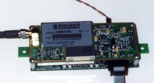
The CM 900 is designed around the Radio CRM 4100 from Standard Communications. Once interfaced with the 4100, to the user, the entire module looks like a standard RS 232 AT command compatible modem. This allows compatibility with popular software packages like Procomm, Hyper terminal, Bitcom, WinFax etc.
jump to Stand Alone Cell Modem Version
jump to Related Cellular Modem pages
jump to -40 to +85C Cellular Modem page
Cellular Data Modem "OEM" CM 900
Features
Sample Application Areas
Cellular Data Modem CM 900
Specfications
Your package includes:
SIZE
4 7/8" mid hole to mid hole
5 1/2" end to end
3" from outside data connector to outside of power connector
1" thick
jump to PDF file of manual
jump to DOC file of manual
|
Base Station Omni Antenna |
OD4-900 4db gain $105.00 |
|
Base Station Yagi Antenna |
YAG6-900 T or N 6db gain $75.00 |
jump to Magnetic mount antenna page
jump to Mobil antennas
Optional - CM 900 with out Radio unit - for use with external cell phone
What you need to provide:
Installation:
The CM900 is configured as a DCE (e.g. modem). It talks to a PC through the RS 232 cable.
First Time Quick Start
For a typical session, the following may help.
Connect the CM900 (with the CRM 4100 radio) to the PC. Configure the serial port to 9600 bps, 8N1 and Hardware Handshaking.
Power up the unit.
Allow 10 seconds for calibration.
Enter <CR>. This allows the unit to auto-baud to match the speed of the PC.
The CM 900 will respond OK. This exercise must be repeated every-time on power up.
We are now ready to configure the radio.
1) Enter AT+TEST<CR>. The unit will respond OK.
2) Enter AT+MIN=< the MIN allocated><enter> The unit will respond OK.
3) Enter AT+SID=< the SID allocated><enter> The unit will respond OK
4) AT+SYS=02 <CR> The system is set for normal mode.
The radio is now configured and ready for operation.
Please note that radio does NOT have to configured every-time. The above information is stored in the Radio’s non-volatile memory.
Operation:
The CM900 (here after referred to as the modem) is always in one of the two states: the command state or the on-line state. The modem assumes the Command State when power is applied. This state allows the modem to be configured for the particular application. In the Command State, all inputs from the PC are treated as commands . The modem may be set to the on-line state in which all inputs form the PC are treated as data to be shipped over the airwaves and all inputs from the airwaves is treated as received data from the remote end.
Command guidelines
Command lines must begin with the characters AT and end with Carriage Return (CR). Either all upper case or all lower case characters must be used.
Command Buffer
The command buffer is 40 characters.
Each command must be entered separately.
Result Codes
Result codes are responses by the modem to commands. These are shown below:
Code Digit Word Code Meaning
0 OK Command executed without errors.
1 CONNECT Connection at 300 bps
2 RING Ringing signal detected
3 NO CARRIER Carrier lost or never present
4 ERROR Invalid command
5 CONNECT 1200 Connection at 1200 bps
6 NO DIAL TONE Cellular service not available
7,8 not used
9 SERVICE UNAVAILABLE Cellular service is not available.
10 No communication is possible
11 SERVICE AVAILABLE Unit ready for communication
On-line state
The Modem is in on-line state in one of the two conditions:
When the modem is in on-line state, all serial data presented to the radio is transmitted over the air.
Do NOT change communication parameters (e.g. baud rate) in this mode.
To go back to Command State, Escape Sequence (described in this section) is required.
Escape sequence
The sequence of characters to transition from On-line State to the Command State is called the escape sequence.
The sequence is +++
The timing interval between the + signs must be between 250 msecs and 750 msecs.
On receipt of a valid escape sequence, the modem will enter Command State and respond with OK.
Supported AT commands
The basic AT (ATtention) commands used to configure the modem operation are defined in this section. The commands implemented are a subset of the commands used in typical high-speed modems.
Upon power up, the user must enter <CR> <CR> ( carriage return twice ). This allows the modem firmware to detect the RS232 baud speed.
A command line is a string of characters sent from the DTE (e.g. a PC) while the modem is in Command State. A command line has a prefix, a body and a terminator. Each command line must begin with a character sequence AT and must terminate with a carriage return.
The Radio starts the processing of commands only after AT string sequence is received.
Commands entered with out of range parameters will result in ERROR message.
Correct commands will result in OK message.
Following AT commands are supported:
Command Action
1) ATZ<CR>
Resets the modem.
The unit will respond a with initializing message
And then OK
2) ATO<CR>
Go on line.
This is done after the state of the unit is changed from
on-line to command state.
ATO then puts the unit back into on-line state.
3) ATDT XXXX <CR> Cell modem dials out. XXXX(phone number)
4) AT+SYS=xx<CR>
Sets system preference.
(SYS =00 Sets the unit for system B only)
(SYS =01 Sets the unit for system A only)
(SYS =02 Is for normal mode. SID determines preferred system)
(SYS =03 Is for home use only)
5) AT+RSSI?<CR>
Indicates the Received Signal Strength.
Higher the better. Should be > 10H for reliable communication.
6) AT+SERVICE?<CR> Indicates if service is available or not
7) AT+TEST<CR> Puts the unit to test mode.
The next three commands are accepted Only after the unit is put into test mode.
8) AT+MIN=XXXXX<CR> Sets the MIN number. The modem responds OK
9) AT+SID=XXXX<CR> Sets SID. Modem responds OK
10) AT+ID?<CR> Displays ESN, MIN, SID,
System Preference information.
Note: MIN, ESN, SID information are stored in the non-volatile memory of the cell-modem. These do not have to be entered every-time on power-up.
11) AT+BAT?<CR>
Indicates battery level in hex format.
00= zero and 64 H = 100%
12) AT&V<CR> Displays settings of the cell modem
13) ATI3<CR> Displays Software Revision #
14) ATH0 Modem disconnects and initializes
15) ATV0 Unit responds in terse mode. Results code Displayed as digits
16) ATV1
Unit responds in verbose mode. Results codes
are displayed as messages.
Escape Sequence:
When the modem is on-line state, it is possible to break the data transmission/reception.
This is achieved by sending a sequence of three ASCII characters. For ease of use, the
default character is +. The Radio will respond with OK on detection of valid escape sequence.
17) +++ Escape sequence OK
Quick Troubleshooting Hints:
ARC ELECTRONICS
a DCE Company
jump to ... Home Page