|
128 port Fiber Mux |
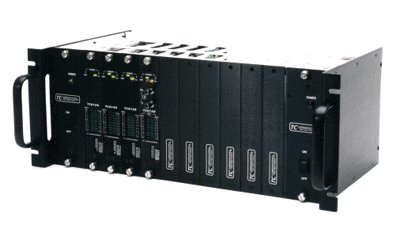
TC8108 Fiber Optic Multiplexer, maximizes user flexibility by offering field interchangeable interfaces, modular expandability from 8 to 64 channels and power/optical redundancy. It supports most popular interfaces including RS-232, RS-422, TTL, RS-485* and Dry Contact Relays.
"Channel
Stacker" 8 - 128 Channel
Fiber Optic Multiplexer
(Model TC8108) Related Products: TC8116

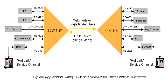
The TC8108 Channel Stacker® is an inexpensive, reliable and flexible method for connecting large numbers of printers, terminals and status collecting devices. It is often used in harsh environments where EMI/RFI interference, ground loops or lightning conditions may exist. The TC8108 can also be used to extend telephone lines to remote locations with the Model TC1900 RS-232/Fiber Phone Extender.

The “Channel Stacker”, Model TC8108 Fiber Optic Multiplexer, maximizes user flexibility by offering field interchangeable interfaces, modular expandability from 8 to 64 channels and power/optical redundancy. It supports most popular interfaces including RS-232, RS-422, TTL, RS-485* and Dry Contact Relays. It supports data rates up to 38.4 Kbps*. Power redundancy is standard, optical redundancy is optional. Both feature automatic switchover. Each unit consists of an 8-channel base unit and up to seven optional 8-channel add-on PC Cards. These PC Cards can be “Stacked” (in 8-Channel increments) up to 64 Channels. A 128-Channel version is possible by using a fan-out cable to expand each RJ-11 port into two RS-232 Async channels.
Because the electrical interfaces are modular, they are interchangeable at any time--before or after installation. A user can mix up to four different interfaces (in 2-Channel increments) on each 8-Channel card. Each PC expansion Card is identified by a card number defined by a front panel DIP switch.
Diagnostics are extensive and include Local and Remote Loopback, 22 LEDs, and a Test Signal Generator. LEDs include “Tx”, “Rx”, “Alarm”, “Vcc”, “RxA”, “RxB”, & “PWR”. Individual “Tx” and “Rx” LEDs are provided for each channel. The built-in test signal generator verifies both device and fiber optic link operation. This feature benefits users by helping technicians verify that both local & remote devices and the fiber optic link are operating normally. No other test equipment is required for link and device verification.
The TC8108 is compatible with all types and sizes of multimode (850/1300nm) or single mode (1300/1550nm) fiber optic cable. Fiber optic connectors are ST or FC; electrical connectors are RJ-11. Power is 12VDC or 115/230VAC with an external power cube. An extreme temperature version (-20° to 70°C), Model TC8108T, is also available.
Fiber optic connectors are ST; FC is optional. Electrical connectors are RJ11. Power is 9 to 12VDC or 115/230VAC with a power card (Model TCRMPS-01) or a power cube.
*Contact factory for higher requirements/availability.
Specifications
|
Data Rates
(per channel) |
Electrical |
jump to
related
mux page
jump to
related fiber page
ARC ELECTRONICS
301-924-7400 EXT 25
jump to ... Home Page
arc@arcelect.com